Connector Pinout
This section lists the connectors with their pinouts.
Table of contents
- J1/J2 - Stepper 1 Output / Stepper 2 Output
- J4 - USB
- J5/J7 - Fan 1 / Fan 2
- J6 - Pump
- J8 - LCD
- J10/J11 - DS18B20 Temperature Sensor 1 and 2
- J12 - Case Detector, Drop Solenoid
- J13 - Rotary Encoder, Start/Stop Button and Home switch
- J14 - ZVS FET Control
J1/J2 - Stepper 1 Output / Stepper 2 Output
| Pin No. |
Function |
Description |
| 1 |
Driver A2 |
Stepper Motor Pin A2 |
| 2 |
Driver A1 |
Stepper Motor Pin A1 |
| 3 |
Driver B1 |
Stepper Motor Pin B1 |
| 4 |
Driver B2 |
Stepper Motor Pin B2 |

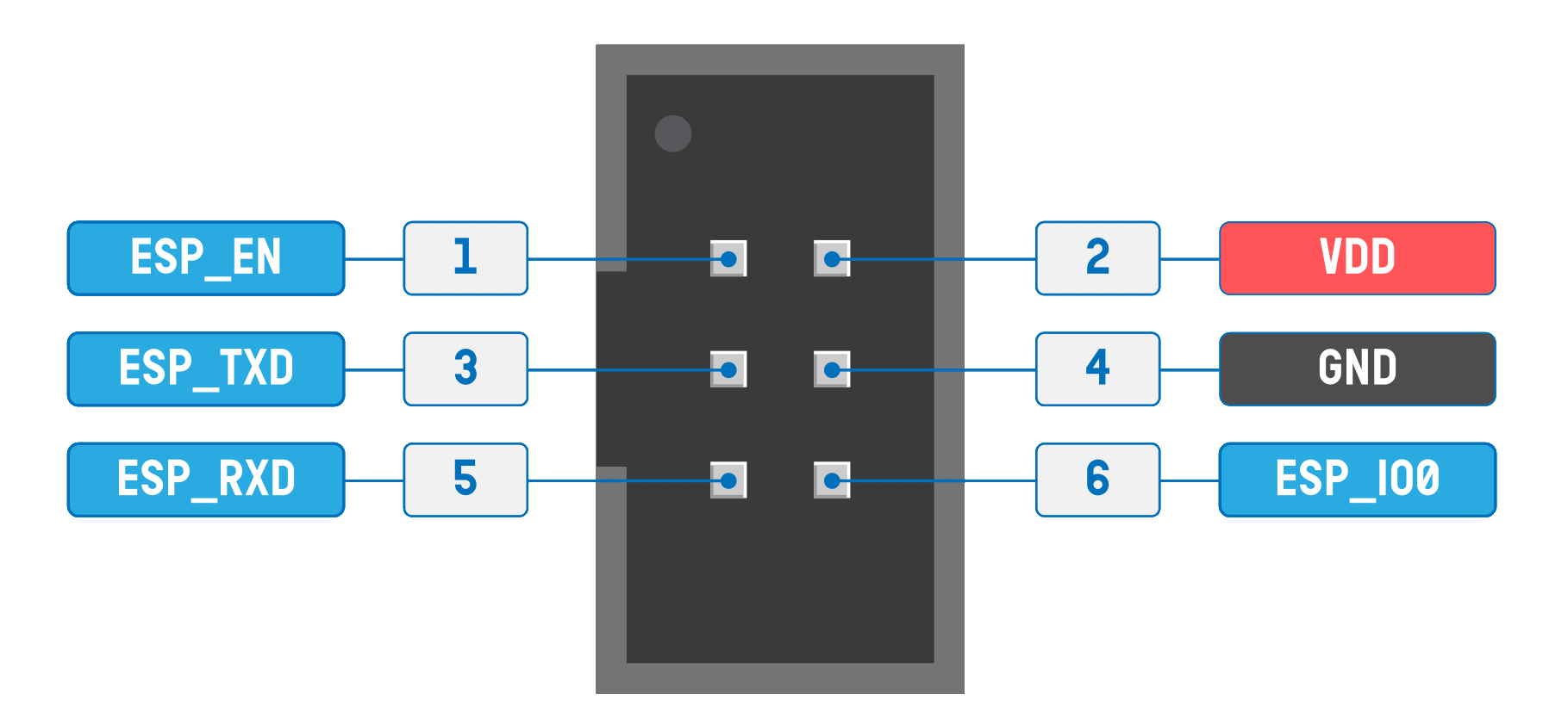
| Pin No. |
Pin Name |
Description |
| 1 |
ESP_EN |
Connects to the RST pin of the target ESP32. |
| 2 |
VDD |
Supply voltage from ESP-Prog. Can be 3.3V or 5V. |
| 3 |
ESP_TXD |
Connects to TXD0 pin of ESP32. |
| 4 |
GND |
Ground/Negative supply pin. |
| 5 |
ESP_RXD |
Connects to RXD0 pion of ESP32. |
| 6 |
ESP_IO0 |
Connects to GPIO0 (Boot) pin of ESP32. |
J4 - USB
| Pin No. |
Function |
ESP32-S3 GPIO# |
Description |
| 1 |
5V |
|
USB 5V |
| 2 |
D- |
19 |
USB Data - |
| 3 |
D+ |
20 |
USB Data + |
| 4 |
GND |
|
Ground |
J5/J7 - Fan 1 / Fan 2
| Pin No. |
Function |
ESP32-S3 GPIO# |
Description |
| 1 |
GND |
48 |
Fan Ground through Low-side Switch |
| 2 |
12V |
|
Fan 12V Supply |
| 3 |
Tach |
|
Not Coonected |
| 4 |
Speed Control |
|
Not Connected |
J6 - Pump
| Pin No. |
Function |
ESP32-S3 GPIO# |
Description |
| 1 |
GND |
47 |
Pump Ground through Low-side Switch |
| 2 |
12V |
|
Pump 12V Supply |
| 3 |
Tach |
21 |
Fan Tachometer Output |
| 4 |
Speed Control |
|
Not Connected |
J8 - LCD
| Pin No. |
Function |
ESP32-S3 GPIO# |
Description |
| 1 |
3V3 |
|
3V3 LCD Power |
| 2 |
LCD Backlight |
3 |
LCD Backlight control. Low-side switch for LCD Backlight GND |
| 3 |
LCD Reset |
17 |
LCD Reset |
| 4 |
LCD A0 |
16 |
LCD A0 |
| 5 |
SPI CS |
15 |
SPI CS for SPI LCD |
| 6 |
SPI CLK |
7 |
SPI CLK for SPI LCD |
| 7 |
SPI MOSI / I2C SDA |
6 |
SPI MOSI for SPI LCD or I2C SDA for I2C LCD |
| 8 |
SPI MISO / I2C SCL |
5 |
SPI MISO for SPI LCD or I2C SCL for I2C LCD |
| 9 |
3V3 |
|
3V3 when using I2C LCD |
| 10 |
GND |
|
Ground |
J10/J11 - DS18B20 Temperature Sensor 1 and 2
| Pin No. |
Function |
ESP32-S3 GPIO# |
Description |
| 1 |
3V3 |
|
3V3 |
| 2 |
GND |
|
Ground |
| 3 |
DQ |
40 |
DS18B20 One-Wire Data |
J12 - Case Detector, Drop Solenoid
| Pin No. |
Function |
ESP32-S3 GPIO# |
Description |
| 1 |
3V3 |
|
3V3 for Case Detector |
| 2 |
Case Detector In |
37 |
Case Detector Input |
| 3 |
Case Detector Out |
36 |
Case Detector Low-Side Switch |
| 4 |
GND |
|
Ground for Case Detector |
| 5 |
GND |
|
Ground |
| 6 |
12V |
|
Drop Solenoid 12V Out |
| 9 |
Drop Solenoid Out |
35 |
Drop Solenoid Ground through Low-side switch |
| Pin No. |
Function |
ESP32-S3 GPIO# |
Description |
| 1 |
3V3 |
|
3V3 for Rotary Encoder |
| 2 |
ROT A |
8 |
Rotary Encoder Pin A |
| 3 |
ROT B |
18 |
Rotary Encoder Pin B |
| 4 |
ROT SW |
4 |
Rotary Encoder Switch |
| 5 |
GND |
|
Ground |
| 6 |
Start/Stop |
44 |
Start/Stop Button. Shared with RXD0 pin |
| 7 |
GND |
|
Ground |
| 8 |
Home Switch |
43 |
Case Height Adjustment Home Switch. Shared with TXD0 pin |
| 9 |
GND |
|
Ground |
J14 - ZVS FET Control
| Pin No. |
Function |
ESP32-S3 GPIO# |
Description |
| 1 |
|
|
No Connect |
| 2 |
FET1 Gate |
46 |
Connect to ZVS Board FET 1 Gate |
| 3 |
FET2 Gate |
46 |
Connect to ZVS Board FET 2 Gate |
| 4 |
FET3 Gate |
46 |
Connect to ZVS Board FET 3 Gate (If it has more than 2 FETs) |
| 5 |
FET4 Gate |
46 |
Connect to ZVS Board FET 4 Gate (If it has more than 2 FETs) |
